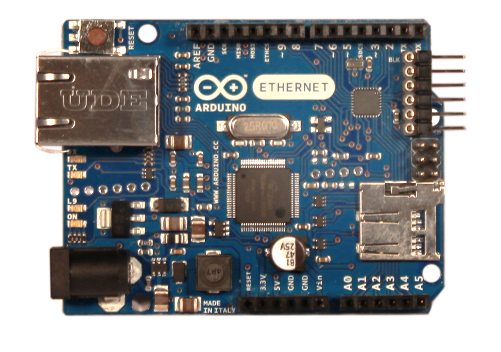
Arduino Ethernet solderpad
A microcontroller board based on the ATmega328
arduino.cc/en/Main/ArduinoBoardEthernetDescription

The Arduino Ethernet is a microcontroller board based on the ATmega328 (datasheet). It has 14 digital input/output pins, 6 analog inputs, a 16 MHz crystal oscillator, a RJ45 connection, a power jack, an ICSP header, and a reset button.
NB: Pins 10, 11, 12 and 13 are reserved for interfacing with the Ethernet module and should not be used otherwise. This reduces the number of available pins to 9, with 4 available as PWM outputs. An optional Power over Ethernet module can be added to the board as well.
The Ethernet differs from other boards in that it does not have an onboard USB-to-serial driver chip, but has a Wiznet Ethernet interface. This is the same interface found on the Ethernet shield.
An onboard microSD card reader, which can be used to store files for serving over the network, is accessible through the SD Library. Pin 10 is reserved for the Wiznet interface, SS for the SD card is on Pin 4.
Schematic

Board

Bill of Materials
| Designator | Value | Description |
|---|---|---|
| 100M | Green | LED |
| C1 | 100n | CAPACITOR, European symbol |
| C2 | 100n | CAPACITOR, European symbol |
| C3 | 100n | CAPACITOR, European symbol |
| C4 | 100n | CAPACITOR, European symbol |
| C5 | 100n | CAPACITOR, European symbol |
| C6 | 100n | CAPACITOR, European symbol |
| C7 | 100n | CAPACITOR, European symbol |
| C8 | 10u | POLARIZED CAPACITOR, European symbol |
| C9 | 22p | CAPACITOR, European symbol |
| C10 | 10n | CAPACITOR, European symbol |
| C11 | 10u | POLARIZED CAPACITOR, European symbol |
| C12 | 22p | CAPACITOR, European symbol |
| C13 | 10u | POLARIZED CAPACITOR, European symbol |
| C14 | 470u | POLARIZED CAPACITOR, European symbol |
| C15 | 1u | CAPACITOR, European symbol |
| C16 | 100n | CAPACITOR, European symbol |
| C17 | 100n | CAPACITOR, European symbol |
| C18 | 10u | POLARIZED CAPACITOR, European symbol |
| C19 | 10u | POLARIZED CAPACITOR, European symbol |
| C20 | 100n | CAPACITOR, European symbol |
| C21 | 100n | CAPACITOR, European symbol |
| C22 | 1u | CAPACITOR, European symbol |
| C23 | 100n | CAPACITOR, European symbol |
| D1 | M7 | DIODE |
| D2 | 4148 | DIODE |
| D3 | SS1P3L | |
| FULLD | LED | |
| IC1 | CAT811TTBI-CT3 | |
| IC2 | ATMEGA328-20MU | MICROCONTROLLER |
| IC3 | 74LVC1G125DCK | Single Bus Buffer Gate with 3-State Output |
| IC4 | MC33269ST-5 | Adjustable Output Low Dropout Voltage Regulator 800 mA |
| IC5 | LM2736Y | |
| IC6 | W5100 | |
| IC10 | 74LVC1G125DCK | Single Bus Buffer Gate with 3-State Output |
| IC11 | 74LVC1G125DCK | Single Bus Buffer Gate with 3-State Output |
| IC12 | 74LVC1G125DCK | Single Bus Buffer Gate with 3-State Output |
| IC13 | 74LVC1G14DBV | Single Schmitt-Trigger Inverter Gate |
| ICSP | ICSP | PIN HEADER |
| J1 | PIN HEADER | |
| J2 | PIN HEADER | |
| J3 | PIN HEADER | |
| J4 | PIN HEADER | |
| L | Green | LED |
| L2 | 4u7 | INDUCTOR, American symbol |
| L3 | BLM21 | SMD EMI Suppression Ferrite Beads |
| L4 | BLM21 | SMD EMI Suppression Ferrite Beads |
| LINK | Yellow | LED |
| ON | Green | LED |
| POWER | PIN HEADER | |
| Q1 | 25MHz | CRYSTAL |
| Q2 | 25MHz | CRYSTAL |
| Q3 | 25MHz KX-7 | |
| R1 | 10k | RESISTOR, European symbol |
| R2 | 300R 1% | RESISTOR, European symbol |
| R3 | 12k 1% | RESISTOR, European symbol |
| R4 | 1M | RESISTOR, European symbol |
| R5 | 100k | RESISTOR, European symbol |
| R6 | 16K5 | RESISTOR, European symbol |
| R7 | 10k | RESISTOR, European symbol |
| R8 | 0R | RESISTOR, European symbol |
| R9 | N.M. | RESISTOR, European symbol |
| R10 | N.M. | RESISTOR, European symbol |
| R11 | 10k | RESISTOR, European symbol |
| R12 | 10k | RESISTOR, European symbol |
| RESET2 | TS42 | TS42 |
| RN1 | 1k | Array Chip Resistor |
| RN2 | 49R9 | Array Chip Resistor |
| RN3 | 1k | Array Chip Resistor |
| RX | Yellow | LED |
| TX | Yellow | LED |
| U$1 | POE-RJ45 | |
| U$2 | FIDUCIALMOUNT | |
| U$4 | FIDUCIALMOUNT | |
| U$5 | FIDUCIALMOUNT | |
| X1 | DC21MMX | |
| X2 | SDCARD-15TW-8821 | SD Card |
| Y1 | 16Mhz | |
| ZZ1 | AG9XX0 | PoE module |
[JSON]
This project is © Arduino™, and is published under the terms of the Creative Commons Attribution-ShareAlike 2.5 Generic licence.