Description

A tweak of the blinking LED, a 555 Timer circuit to alternate between a pair of LEDs, a bit like a railway crossing signal.
[video]
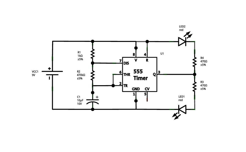
Schematic
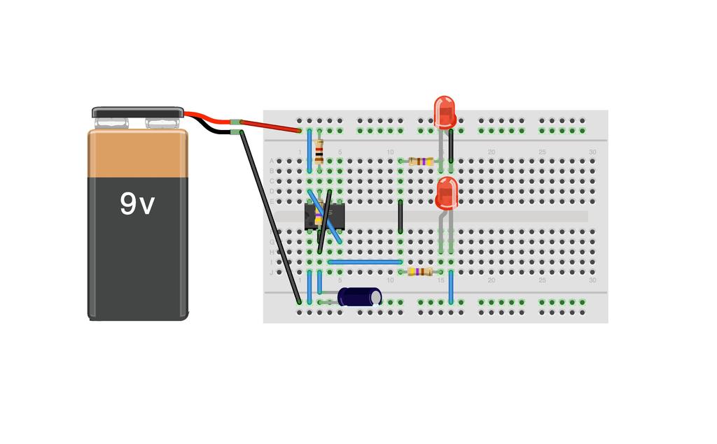
Board
Bill of Materials
| Designator | Value | Description |
|---|---|---|
| C1 | 10µF | Electrolytic capacitor; 1µF; voltage 10V |
| R1 | 1kΩ | Resistor |
| R2 | 470kΩ | Resistor |
| R3, R4 | 470Ω | Resistor |
| LED1, LED2 | LED-05R | 5mm LED red |
| U1 | NE555 | 555 Timer |
| VCC1 | 9V | 9V battery, PP3 or similar |
[JSON]
This project is published under the terms of the BSD License licence.